Assessment of the relief chamber on Slavojova Street.
Our own assessment method has been thoroughly tested in practice on these relief chambers (RC) of different types:
- Slavojova — slotted relief chamber
- Sekaninova — relief chamber with a side overflow edge
- Na barikádách — relief chamber with a side overflow edge
- Čakovice — vortex separator
- Pod Táborem — relief chamber with a frontal overflow
- OK Teplická in Děčín, which we developed.
In this article, we offer you an insight into these evaluations.
OK Slavojova
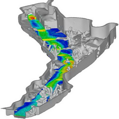
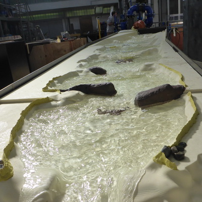
This is a slotted RC with a slot width of 1,500 mm and a drop height of 377 mm between the spill edge and the cutting edge. The inlet channel has a circular profile DN 1430 with a slope of 10.8‰. Under dry conditions, all wastewater is carried away by the outflow channel DN 600. Overflowing wastewater is discharged through an outlet DN 1430 into the Botič river.
As part of the assessment of the RC, we conducted a series of laboratory sediment analyses and mathematical simulations under varying flow rates. We found that the chamber’s impact on the recipient depended on the flow rate and the size of the contamination particles. While particles larger than one millimeter were carried along the bottom and almost all were discharged through the sewer network, smaller particles were evenly distributed in the flowing wastewater, thus being divided proportionally to the flow distribution.
Laboratory analyses revealed that the influence of the relief chamber resulted in an increase in the concentration of heavy metals, a change in grain size, and a change in the percentage representation of heavy metals in the individual fractions beneath the relief chamber.
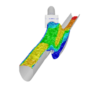
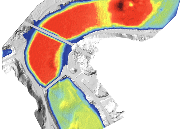
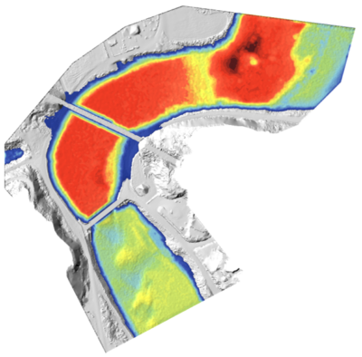
By comparing simulations of different flow conditions, we reviewed the dependency of the effectiveness of suspended solids separation on the flow rate.
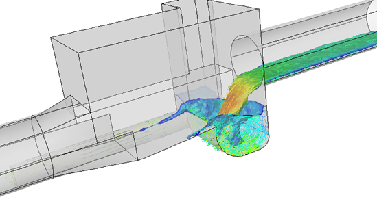
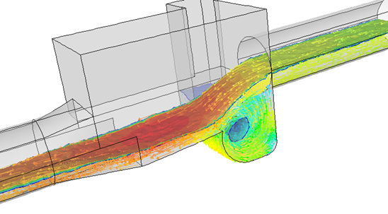
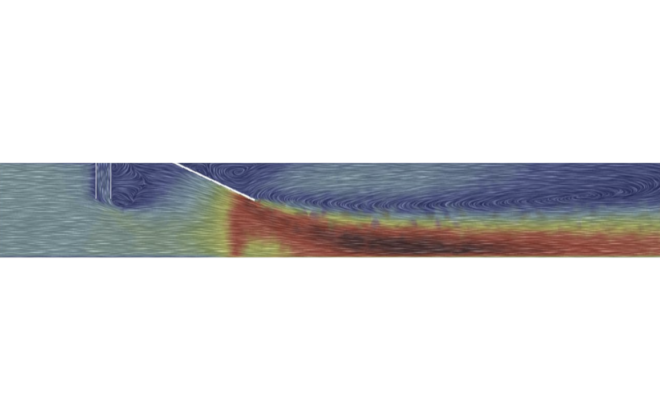
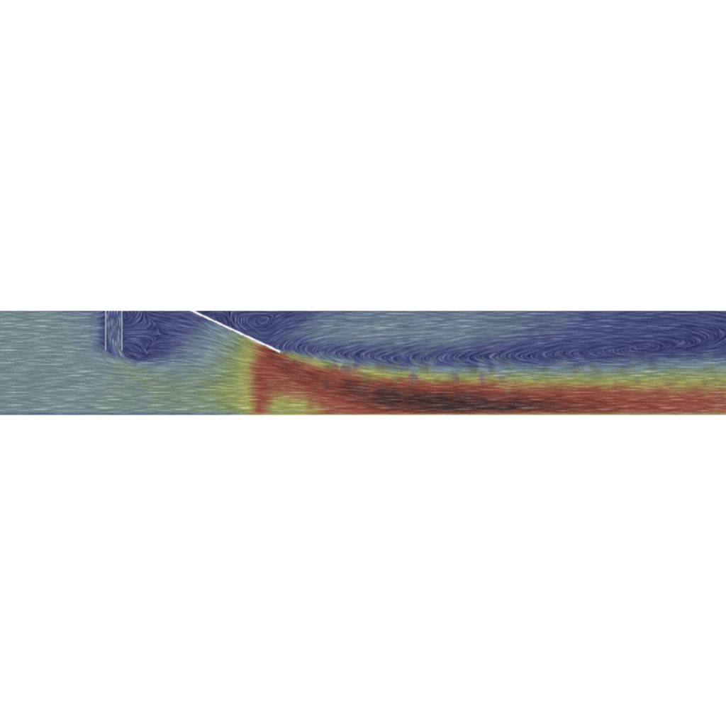
At very low flow rates, the relief chamber showed high efficiency. However, as the flow rate increased, the efficiency dropped sharply (see the graph below). This was primarily due to strong swirling in the area of the outflow behind or in front of the dividing edge. The chamber did not remove floating substances at all.
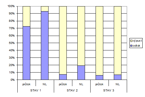
The graph compares the unit mass ratios of pollution (NL) with the flow ratios before and after the relief chamber, depending on the flow conditions. Further numerical simulations showed that at higher flow rates, the suspended solids did not have enough time to settle, and thus most of them overflowed along with the wastewater into the receiving body.
Related items
Pipe mixer
Analysis of the consumption curve of the channel and flood flows
Design of the reconstruction of the slalom channel in Ivrea